Contact: John Tao
Mobile/WhatsApp: +86 186 6862 7050
Email. Johntao@Fupusi.com
www.Fupusi.com
John Tao as the owner of Taizhou Fupusi Machinery Co., Ltd., who has more than 15 years of experience in the plastic bottle industry field, is focused on improving the quality of the machines and the after-sales system
V. Seasonal maintenance -1500 hours:
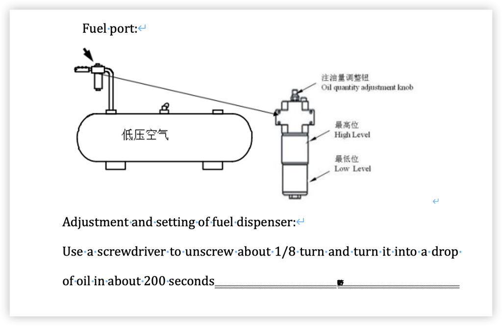
- Work pressure:
Check the pipelines and compressors of the operating system. Check if the pressure gauge is malfunctioning. - Blowing pressure:
Check the pipelines and compressors of the high-pressure system. Check the internal filters of the system. - Cooler:
Test the temperature of the cooling water.
Check the cooling water pipeline.
Update the circulating water of the chiller unit and add appropriate softeners, dust proofing agents, antifreeze agents, etc. To ensure smooth pipeline flow and stable quality. - Cooling water tower:
Test the temperature of the cooling water.
Update the circulating water in the cooler and add appropriate softeners, dust proofing agents, antifreeze agents, etc. To ensure smooth pipeline flow and stable quality. - Cleaning:
Use filtered dry air to remove dust from the material handling machine and conveyor belt, and wipe with a dry cloth. - Check the support bolts of the machine and measure their flatness.
- Mechanical:
Check the bolts on the feeding and unloading robotic arms to ensure they are securely fixed. - Follow up bearings:
The bottom mold drive bearing CF12-1 should be regularly inspected and maintained. If there is wear, it should be replaced in a timely manner.
VI. Annual maintenance -6000 hours:
- Electrical cabinet:
Check all fuses.
Ensure that every connection of the screws is tightened. - Infrared light:
The lifespan of an infrared lamp at 380 volts is 5000 hours.
Long term low output increases the lifespan of infrared lamps. - High pressure muffler:
Take out the high-pressure muffler, blow off the dust with filtered dry air, and then wipe it with a dry cloth. - Bolt tightening:
Check all bolts to ensure they are securely fastened. - Air pressure system:
Test the sealing of pneumatic cylinders, control valves, pressure gauges, pipelines, and connections. Use soapy water to test for air leaks.
Check the performance of the safety valve and adjust the above pressure, preset the pressure to ensure its normal operation.
VII. Update on infrared lights:
service life:
The specifications of the lamp are 220V-235V, 1000W, and 1000W under 235V output conditions, with a service life of 5000 hours. - Update
Attention: When replacing the lamp, as the lamp and heating oven are very hot, maintenance personnel must wear heat-resistant protective clothing and gloves for safe replacement.
(1) Turn off the main power supply of the electrical cabinet.
(2) Open the safety door and loosen the bolts of the junction box protective cover.
(3) Remove the coils from both ends of the lamp.
(4) Remove the movable pins on both sides of the heating furnace and gradually lower the heating furnace.
(5) Carefully remove the damaged lamp and replace it with a new one.
(6) Rotate the heating furnace upwards to position and insert the movable pin to fix the heating furnace.
(7) Connect the cable of the lamp to the distribution board and tighten the bolts of the protective cover.
(8) Close the safety door and turn on the power.
(9) Turn on the temperature controller and check if the light is working properly.
(10) Restart and run.
matters needing attention:
When replacing lighting fixtures, please keep the surface of the fixtures clean. If there is dirt on it, wipe it with cotton soaked in alcohol.
Before updating, first check how many lights are broken in the electrical cabinet
V. Maintain and inspect safety:
Attention: When performing maintenance, be sure to follow the regulations, otherwise the machine and peripheral devices are easily damaged.
When performing maintenance or repair, be sure to cut off all power sources and hang a “Do Not Use” signal. Use an electricity meter to check if there is a power source “on”. Before starting work, open the drain valve by hand, ensure that the pressure gauge is 0 kgf/cm2, and lock the intake valve. If the machine needs maintenance, it must be hung on a “maintenance” billboard.
The set pressure of the exhaust valve within the air pressure is adjusted by the manufacturer. If the pressure gauge exceeds the high pressure specified by our company, the service life of this machine will be shortened.
In order to protect the safety of operators, the movable parts of the machine are designed with safety doors and heating furnace protective covers. Don’t take it away casually. During operation, the safety door and electrical control cabinet door must not be opened and should be checked daily.
When adjusting the air pressure system or template, be careful not to be scratched by the chuck.
- Pneumatic components used on the machine, such as air storage tanks, air pressure regulators, safety valves, cylinders, pipeline connections, and high-pressure pipelines. When replacing, reduce the high voltage to 0 kgf/cm2 and confirm that the template has been separated. After operation or regular maintenance, soap water should be applied to the composite components to check for air leaks. Check the safety valve of the pneumatic system every six months.
When the stretching blow molding machine or electrical system needs maintenance or repair, be sure to keep the power switch in the “off” position. If there is a key device, please lock it to ensure safety. - Check for water leaks at all times, especially electrical components, and do not allow water connections. Molds, heating furnaces, etc. all require water. When maintaining or repairing, it is necessary to check whether the connecting components are leaking water? When disassembling or replacing the mold, be sure to completely drain the water.
- Refuel or replace the stretch blow molding machine to ensure it is in a stationary state.
- Use standard tools for maintenance, repair, and inspection, such as bolts and screws that should be securely fastened with appropriate torque.
- The parts, consumables, watches or instruments of the stretch blow molding machine should be inspected regularly.
When conducting electrical maintenance or repairs while powered on, it is essential to use insulation materials or equipment (such as clothing, shoes, gloves, and safety helmets) and insulation tools (such as screwdrivers and clips) for protection. Remove metal items such as rings, bracelets, necklaces, etc. and operate safely. Two people participate in maintenance and repair to ensure safety.
When resting, be sure to cut off the main switch power supply. - Do not touch electrical equipment with wet hands.
- The water and air pipes in the factory should meet the specifications of our stretch blow molding machine. In addition, pressure standards and equipment should comply with the prescribed specifications. High pressure pipelines and regulator joints must comply with high pressure specifications, pressure resistant materials, and structures.
- Electrical equipment and related wiring should meet the following requirements:
(1) Before operation, appropriate grounding plates and grounding connectors should be connected to the designated location or body.
(2) Use fuses of the correct capacity.
(3) The capacity of relevant electrical components should comply with the specifications for insulated cables.
VI. Safety precautions for management personnel:
- All live working personnel should receive education on safety content.
- Machine maintenance administrators should possess all relevant knowledge and training.
To ensure safety, it is recommended to have at least two people participate in operation and maintenance. - According to our safety requirements, use in conjunction with other accessories. Please do not replace molds or peripheral devices at will.
To ensure safe and efficient operation, the machine should be inspected at least once every five years after debugging.
To ensure operational safety, safety devices or safety valve isolators must not be removed or replaced during any normal operation.
VII. Laws and regulations:
The operation of this machine is subject to laws and regulations such as high-pressure gas treatment, fire protection laws, and worker safety and health regulations. It is necessary to carefully read these laws and regulations and seek advice from organizations related to the safe handling of high-pressure gases and other hazardous substances, as well as authoritative industrial accident prevention associations.
VIII. Material and smoke issues:
Heating polymers and their additives to the recommended processing temperature range may produce toxic fumes. Evaluating the smoke generated by a given polymer/additive mixture requires information from all relevant material suppliers.
The provision of personal protective equipment and the local and general ventilation required to minimize harmful smoke concentrations should be evaluated.
In the machine, there is an exhaust fan above the heating furnace that can be connected to a 6-inch ventilation duct to expel hot air and harmful smoke.
IX. Fire extinguisher:
Mechanical equipment should be installed near fire-fighting equipment to prevent fires
Firefighting equipment should use carbon dioxide pressurized powder type.
X. Dismantling the machine:
When disassembling the machine or its parts, be sure to check the high and low pressure air systems. Ensure that the pressure air has been released and the pressure gauge indicates zero kgf/cm2.
II. Precautions for operation:
I. Precautions before machine operation:
- Coupling of three-phase power cables:
- Please ensure the direction of the motor in the following three situations: (1) During trial operation (2) After electrical maintenance (3) After the machine is moved After operation, be sure to confirm the direction of the motor and set the power to the “on” position to observe whether the rotation direction of the motor is correct. When the rotation direction of the motor is different, replace the two cables and retest.
- Safety device inspection:
·Before operation, please check the safety device,
For example: safety doors, fuses, etc., to avoid any accidents, check the emergency stop device. - Check the lubricant:
·Check the oil level in the working pressure filter. ·Ensure that each slider lubricant is sufficient? - Mold inspection:
·In the operating environment, the mold should be clean and not placed on other items. - Air pressure check:
·The maximum working pressure is 8 kgf/cm2
The maximum blowing pressure is 35 kgf/cm2 - Machine stop:
After operation, temporarily stop working or cut off the power supply. In order to ensure the safety and service life of the parts, it is necessary to cut off the main power supply.
- Safety device inspection:
II. Precautions before and during operation:
Before operating the stretch blow molding machine, please read this manual carefully.
After reading the safety signals and alarm content, operate this stretch blow molding machine.
- All screws, nuts, and shafts of the stretch blow molding machine are metric.
- After opening the safety protector and door, confirm that the motor has been turned off.
- Ensure that the emergency stop function is functioning properly.
When maintaining or repairing electrical cabinets, operation boards, terminal boards, and infrared lights, be sure to cut off the power supply.
When maintaining, fixing, and installing machine molds, moving parts should be placed in fixed blocks. When entering the machine, make sure there is no movement. It is necessary to work with two or more technical personnel.
When working inside or on the upper part of the machine, ensure that the motor is turned off and the main power is cut off. Please have two or more technical personnel continue to operate. - Regularly check whether the fixing screws and other screws of the mold cylinder are loose?
- When installing the mold, cut off the main power supply, lower the cylinder, and stop supplying high-pressure air.
- Limit switches used for safety doors and electrical control cabinets must not be short circuited, resulting in operational failure; Otherwise, danger can easily occur.
III. Check:
Confirm the following during installation. - Electrical part:
(1) Is the grounding wire well connected?
(2) Is the rotation direction of the motor correct?
(3) Is there any leakage phenomenon?
(4) Is the emergency stop function functioning properly?
(5) Does the motor and all actions stop when the safety door is opened?
(6) Is the terminal loose?
(7) Is the electrical switch loose?
(8) Is the infrared light loose or damaged?
(9) Is the solenoid valve coil loose?
(10) Is the fuse broken?
(11) Is the main power supply cut off during maintenance?
(12) Has the voltage decreased? - High pressure air section:
(1) Are the buffers of various cylinders adjusted properly?
(2) Check if the air pressure circuit, dehumidification, and oil removal of the stretching blower are correct.
(3) Check if the lubricating oil capacity of the pressure circuit is insufficient.
(4) Is the pipeline broken or loose?
(5) Are the coils and fixing bolts of the electromagnetic control valve loose?
(6) Is the air pressure maintained at 0 kgf/cm2 during maintenance or repair? Is the safety block placed between the templates during operation?
(7) Is there an air leak? - Machine parts:
(1) Are the bolts and nuts of each component loose?
(2) Is the supply of lubricating oil and grease sufficient?
(3) Are the positions for stopping and starting the circuit correct?
(4) Is the height of the prefabricated support the same as the mold? Is the C-shaped snap ring loose?
(5) Is the telescopic rod loose?
(6) Is the speed of the mold correct?
(7) Is the installation interpreted correctly?
(8) Is the cooling water flowing smoothly, and is the water circulation ramp inside the heating furnace deformed?
(9) Are there water droplets on the molds and machines?
(10) Is there any oil contamination at the discharge location?
(11) Is the extension rod and air pressure contaminated with oil?
(12) Are the screws of the heating furnace firmly fixed?
III. Installation
1、 Machine installation:
matters needing attention:
In order to ensure the normal operation of this machine, the accessories and connections of this machine are the most important tasks. Conduct separate tests on conveyors, loosening machines, air compressors, and cooling towers.
This machine is designed with emergency stop devices, safety doors, etc. When an emergency occurs, all air circuits can be closed. In addition, the performance of each cylinder should be set to avoid any accidents. The other precautions in this manual should be carefully read and fully understood to ensure the safety of the operator in a safe working environment.
To ensure product quality and machine lifespan, please install the machine in an air conducting space and set the temperature between 20 ℃ and 25 ℃, and the humidity between 20% and 40%.
(1) Stretch blow molding machine CH: Cold water
(2) Compressor (high pressure) CL: cooling tower
(3) Compressor (for low pressure) high pressure air
(4) The cooler compresses the air
(5) Cooling tower
1 Machine movement and installation: The lifting box carries the movement of the machine. This is an important task, so please give it full attention. (1) The machine weighs about 6500 kg and the lifting box weighs 10 tons. The method of lifting the machine is shown in the following figure.
(1) The machine weighs approximately 6500 kilograms and the lifting box weighs 10 tons. The method of lifting the machine is shown in the following figure.
(2) When transporting, pay attention to the center of gravity position to avoid damaging the machine.
(3) In order to maintain the optimal state of machine installation, the foundation provided for installation should be firm.
(4) Before installation, please consider the surrounding space of the machine. Therefore, there will be no harm to workers or inconvenience to their operations in narrow spaces.
(5) Keep the environment clean during installation. Do not install the machine in a directly exposed or unstable circuit location; Otherwise, the machine will become unstable and its electrical components will be replaced.
(6) Pay attention to safety during installation.
(7) Check if the screws are loose.
(8) After installing the machine, clean the rust proof oil and dirt on it.
(9) After installing the machine, calibrate it with an air level.
(10) The machine should be connected to the ground.
(11) During the installation of the mold, careful attention should be paid to the opening/closing operation and the condition of the surrounding environment.
- Cooling water installation:
(1) The cooling water circulates through the water channel of the heating furnace, with a preset temperature of 30 ℃ and a working pressure range of 2~4kgf/cm2.
(2) Anti corrosion and softening agents should be added to the cooling water to prevent pipeline damage, which can lead to machine damage and worker injury.
(3) The inlet or outlet of the pipeline should be of appropriate size to avoid low pressure. The inner diameter of the pipeline should be greater than 16mm.
- Installation of cooling water:
1 Cooling water is used to cool the mold, with a preset temperature of 10C-12C and a working pressure range of 2-4 kgf/cm2.
2 Antifreeze, preservatives, and softeners, etc. It should be added to frozen water to avoid damage to the pipeline.
3 The diameter of the import or export pipeline should be greater than 16mm to reduce pipeline losses.
4 In order to maintain a stable water temperature, all pipelines must undergo heat insulation treatment to prevent condensation.
Note: The mold water circuit cleaning intake valve is only used for cleaning the water circuit or mold replacement, and for emptying the water circuit
Residual moisture, in addition, please do not open the inlet valve to prevent frozen water from re entering the air compressor system, causing rusting of the air compressor system pipes, impurities, abnormal operation of the cylinder and solenoid valve, and damage
- Install power supply:
(1) The power supply is AC415V, 50HZ, three-phase.
(2) The cable adopts: a single cable with an area greater than 30mm2, and three cables with an area greater than 38mm2. (3) This machine must be grounded, connected to copper nails with a 16 mm2 cable and buried about 1 meter deep underground. The resistance of the grounding connection is less than 100 ohms
(4) Voltage variation is allowed within ± 5%, and a voltage regulator is added to ensure smooth operation and stable quality of the machine.
(5) When the machine is running, pay attention to whether the cable temperature rises abnormally?
(6) After installing the power cable, observe whether the direction of motor operation is consistent with the direction indicated by the arrow.
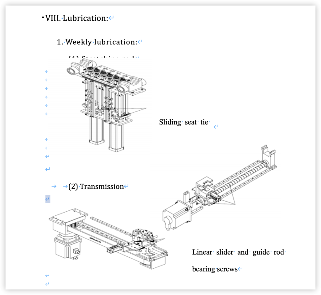
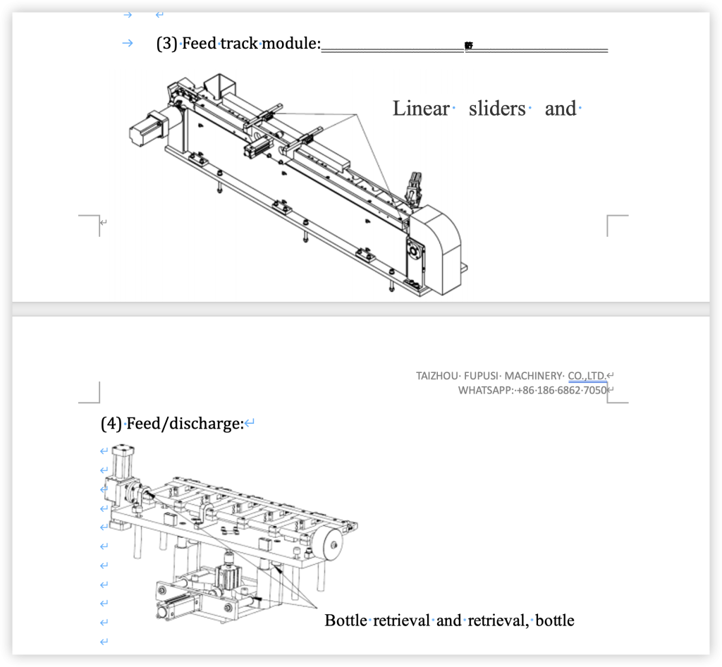
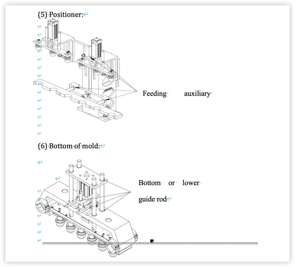
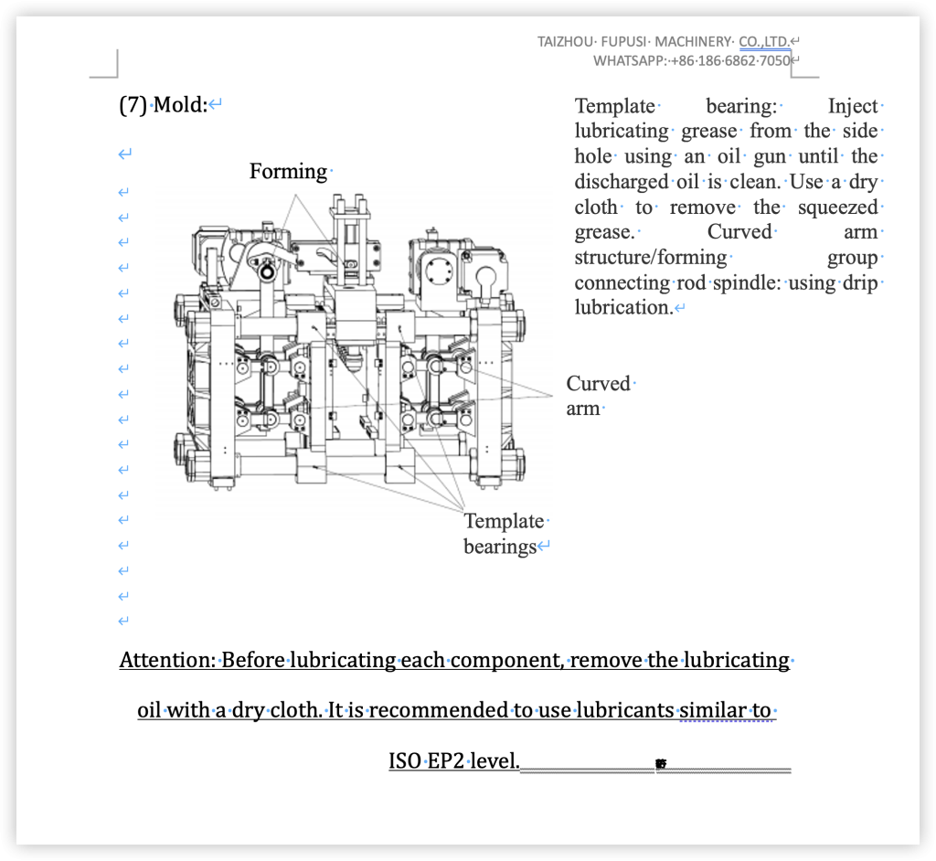
- Lubricants:
(1) The US Food and Drug Administration should provide qualification certification for lubricants used in food machinery.
(2) The sliding part of the grease nipple on the machine should be lubricated in the direction of the arrow
IV. Operation and adjustment:
After setting up, functional testing should be conducted jointly by one person and another.
1 Pre startup inspection:
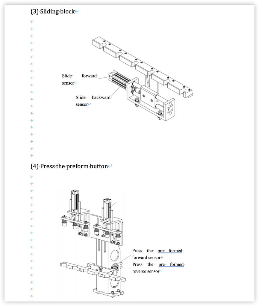
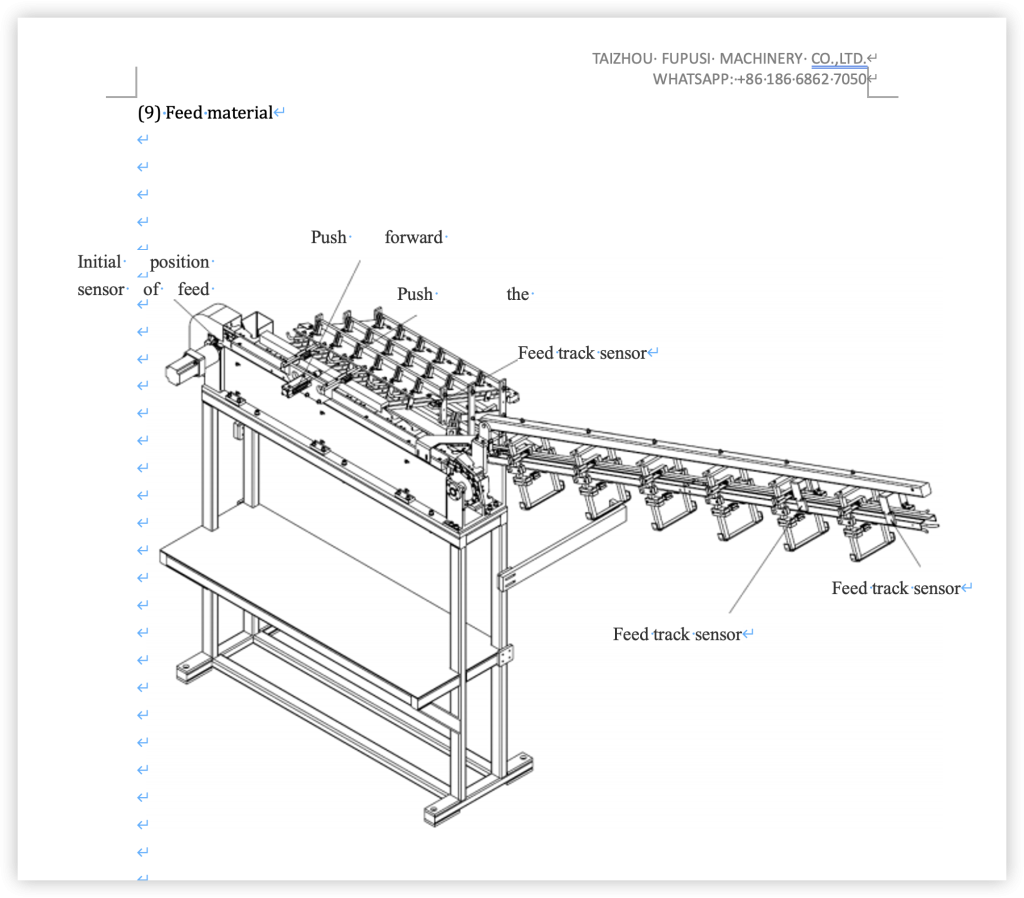
- Photoelectric sensors on the feeding track:
There are two sets of photoelectric sensors in the middle and end of the photoelectric track. The upper photoelectric switch is used to control the feeding time on the conveyor. When the photoelectric sensor measures the pre feed, after a certain time delay, the feed will begin. The lower photoelectric sensor is used to measure the feeding time of the billet on the feeding track. When the photoelectric sensor does not respond to the preform, the conveyor stops and the robotic arm stops grabbing the preform, while the spindle continues to operate.
We need to confirm whether these two sets of photoelectric sensors can respond. Fill the feeding track with the preform and observe if the light of the photoelectric sensor is on. If the light is on, it indicates a normal situation. However, if the light still goes out, it means no reaction has occurred. Loosen the fixing bolts on the sensor, move the position and angle of the sensor until it can respond. Otherwise, the machine will not function properly.